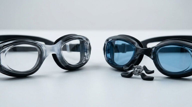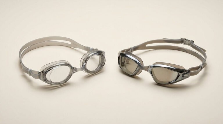
A swimming goggle can look perfect in a CAD rendering but still fail when its components are produced from a real mold.
The lens may warp during molding. The gasket may no longer align with the frame. A small dimensional change can affect assembly or create leakage around the eyes.
Turning a swimming goggle CAD design into a production mold requires six steps: CAD preparation, Design for Manufacturing (DFM) review, pre-tooling validation, mold engineering, T1 trial inspection, and final mold approval.
Each step helps engineers identify problems before they become expensive tooling corrections.
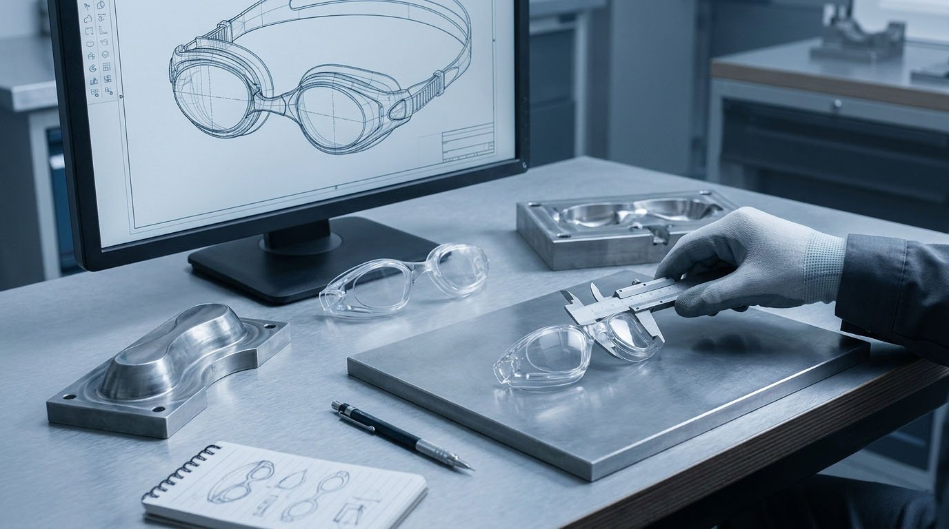
This guide focuses on the engineering work between an approved product concept and a production-ready mold.
For the broader journey from product idea to finished swimming goggles, see our in-house swimming goggle R&D process.
Quick Answer: How Does a Swimming Goggle CAD Design Become a Production Mold?
A CAD file defines the intended geometry, but engineers must convert that design into a mold that can produce consistent, functional components.
The process follows six main steps.
| Step | Engineering Activity | Key Deliverable |
|---|---|---|
| 1. CAD Preparation | Confirm dimensions, materials, and assembly | Approved CAD revision |
| 2. DFM Review | Evaluate molding feasibility and design risks | DFM report |
| 3. Prototype Validation | Check physical fit and assembly before tooling | Pre-tooling approval |
| 4. Mold Engineering | Design and manufacture production tooling | Completed mold |
| 5. T1 Mold Trial | Inspect molded components and identify defects | Trial inspection report |
| 6. Mold Approval | Verify corrections and repeatability | Approved tooling and reference samples |
The critical principle: approving a CAD design does not automatically mean the product is ready for tooling or mass production.
Each engineering stage needs its own review and approval.
Step 1: Prepare the Swimming Goggle CAD Design for Manufacturing
Before mold engineering begins, the manufacturer must confirm that the CAD model contains enough information to define the intended product.
A swimming goggle is an assembly of connected components rather than a single molded part.
Depending on the design, these may include polycarbonate lenses, a frame, flexible gaskets, a nose bridge, strap attachments, buckles, and other adjustment components.
Confirm Component Geometry and Assembly Interfaces
Engineers review the three-dimensional relationships between components.
Important questions include:
- Does the lens fit securely into the frame?
- Does the gasket align with the intended sealing surface?
- Can the nose bridge be installed and adjusted correctly?
- Will strap tension affect the frame geometry?
- Are the component interfaces dimensionally compatible?
These relationships matter because changing one part may require adjustments to another.
For example, increasing the thickness of a lens-retaining feature could affect frame engagement or the position of an adjacent gasket.
Define Materials and Critical Dimensions
Material specifications should be established before the mold design is finalized.
Different materials behave differently during molding, cooling, and assembly.
A polycarbonate lens and a flexible silicone gasket require different engineering considerations, including shrinkage behavior, mold release, and dimensional stability.
The CAD release package should identify the selected materials, critical dimensions, tolerances, surface requirements, assembly interfaces, and drawing revision.
CAD approval should mean the manufacturer and brand are working from the same controlled design—not simply that the product looks attractive on screen.
Step 2: Complete the Design for Manufacturing (DFM) Review
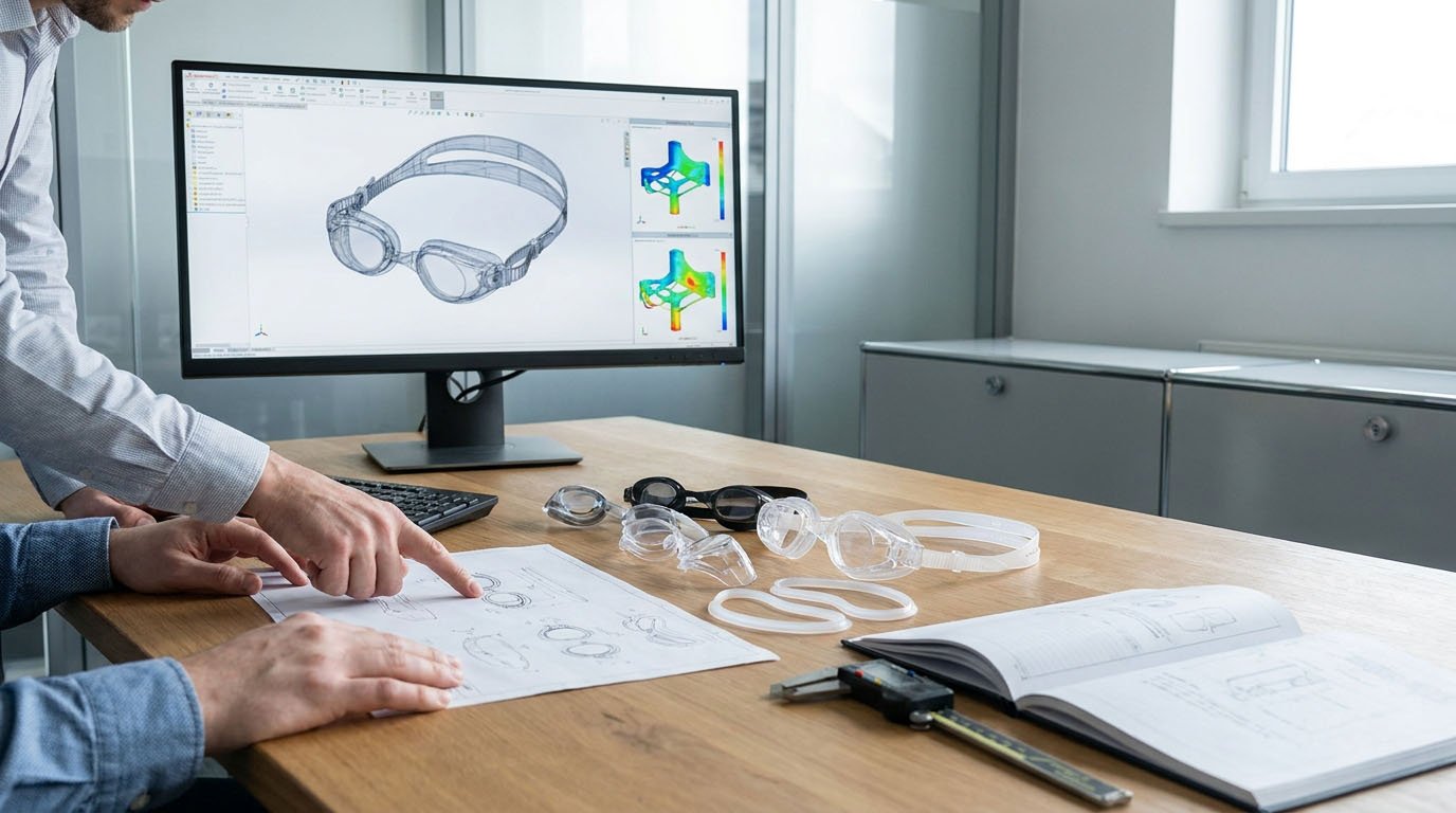
Design for Manufacturing, or DFM, evaluates whether the approved CAD geometry can be produced using the intended manufacturing process.
This is one of the most important checkpoints before cutting mold steel.
Evaluate the Main Molding Risks
For swimming goggles, DFM must consider both individual molded components and the way those components interact after assembly.
| Component or Feature | DFM Check | Potential Risk |
|---|---|---|
| PC Lens | Wall thickness, shrinkage, optical surfaces | Warpage or visual distortion |
| Rigid Frame | Draft angles, parting lines, ejection | Difficult release or dimensional variation |
| Silicone Gasket | Molding feasibility, sealing geometry | Uneven gasket fit or flash |
| Nose Bridge | Dimensional fit, engagement features | Assembly difficulty or poor adjustment |
| Buckle / Strap Connection | Undercuts, retention geometry | Weak engagement or difficult assembly |
The exact checks depend on the product architecture and manufacturing method.
Wall Thickness and Shrinkage
Uneven wall thickness can contribute to differential cooling, internal stress, sink marks, or warpage in thermoplastic components.
Engineers must evaluate whether the geometry supports appropriate material flow and predictable dimensional behavior.
Shrinkage allowances should be based on the selected material, part geometry, and intended molding process—not one universal percentage.
Draft Angles and Mold Release
Draft angles help molded parts release from the tooling.
However, the appropriate draft depends on material behavior, surface finish, part depth, and mold construction.
Some functional surfaces require special attention because even a small geometry change may affect assembly or optical performance.
Gate and Parting Line Placement
The gate controls where material enters the cavity, while the parting line defines where mold sections meet.
Poor positioning may contribute to visible marks, flash, filling problems, or defects near functional surfaces.
For swimming goggles, engineers should pay particular attention to lens surfaces, gasket-contact areas, and component engagement features.
Approve DFM Changes Before Tooling
A DFM review should not end with a verbal statement that the mold can be made.
The manufacturer should document proposed geometry changes, explain their potential effects, and identify which changes require brand approval.
The approved CAD revision then becomes the reference for mold engineering.
Step 3: Validate the Physical Design Before Cutting Steel
Even after a successful DFM review, some design risks cannot be fully evaluated using CAD alone.
A physical prototype can reveal problems involving scale, assembly, facial geometry, or adjustment features.
What Can a Prototype Confirm?
Depending on the prototype method, engineers may use physical models to check component positioning, nose bridge clearance, lens-frame engagement, strap attachment geometry, and overall appearance.
Fit evaluation can also identify obvious pressure-point or positioning concerns before production tooling is manufactured.
These checks are especially useful when developing a new frame or gasket structure.
What Are the Limits of Rapid Prototyping?
A 3D-printed frame or cast elastomer mockup may not reproduce the exact behavior of injection-molded production materials.
For example, a substitute flexible gasket may help evaluate approximate geometry but cannot automatically validate the compression, recovery, or water-sealing performance of the final molded silicone part.
Likewise, a printed transparent lens cannot necessarily represent the optical quality of a polished injection-molded lens.
Physical prototypes reduce design uncertainty, but final performance still requires evaluation using representative molded components.
Establish a Pre-Tooling Approval Gate
Before authorizing mold fabrication, the manufacturer and brand should confirm that the design revision is approved, critical assembly risks are addressed, and remaining validation requirements are documented.
For details about developing and reviewing samples, see Jerry’s Sampling & Prototyping service.
Step 4: Convert the Approved CAD Into Mold Engineering
Once the design has passed its pre-tooling checks, engineers translate the CAD geometry into a manufacturing tool.
This requires more than transferring a digital shape to a CNC machine.
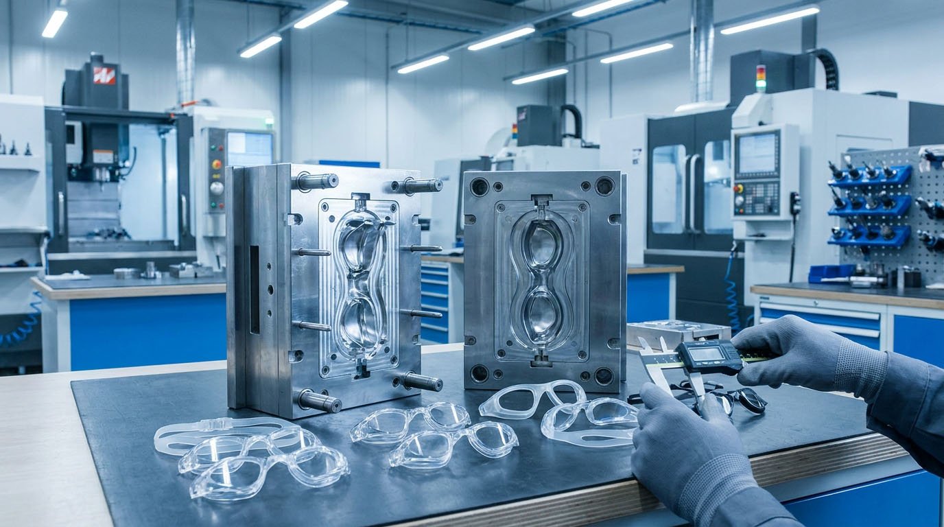
The mold must support material filling, cooling or curing, component release, dimensional stability, and the specified surface quality.
Design the Core, Cavity, and Mold Structure
The mold core and cavity define the surfaces that form the finished component.
Their design must account for the molding process, material characteristics, geometry, and expected production requirements.
For thermoplastic components, engineering decisions may include gate position, cooling layout, venting, and ejection.
Silicone tooling requires considerations appropriate to the selected silicone molding process.
These decisions should not be treated as interchangeable across materials.
Engineer Different Goggle Components Separately
A complete swimming goggle may require several molds rather than one universal tool.
For example, the optical lens, rigid frame, and flexible gasket may each need different tooling approaches.
Precision becomes particularly important where one component must fit another.
A lens that is dimensionally acceptable on its own may still create assembly problems if its interface does not match the frame.
This is why mold engineering must evaluate the assembled product, not only individual parts.
Manufacture and Inspect the Mold
Depending on the tooling design, fabrication may include CNC machining, EDM, finishing, polishing, fitting, and dimensional inspection.
Optical lens molds may require particularly controlled surface finishing to support the intended lens quality.
Manufacturing checks should verify critical tooling dimensions and identify issues before the first molding trial.
How Long Does Swimming Goggle Mold Development Take?
For new custom swimming goggle tooling, Jerry’s development reference is approximately 35–50 days, depending on the number of molds, component complexity, and tooling requirements.
This is a planning reference rather than a guaranteed completion date. The project schedule should clearly identify whether the quoted period includes initial trials and how additional corrections affect delivery.
Complex component interfaces, optical surfaces, or multiple tooling revisions can extend the overall development schedule.
For a detailed explanation of tooling scope, quotations, and ownership considerations, read our Swimming Goggle Mold Cost Guide.
Step 5: Inspect T1 Samples and Correct Mold Defects
Completing the mold does not prove that it will produce acceptable components.
The next step is a physical molding trial.
The first engineering trial is commonly called T1, although some manufacturers use T0 for an earlier initial trial.
Its purpose is to identify the differences between the approved design and the components produced under actual molding conditions.
What Should Engineers Inspect During T1?
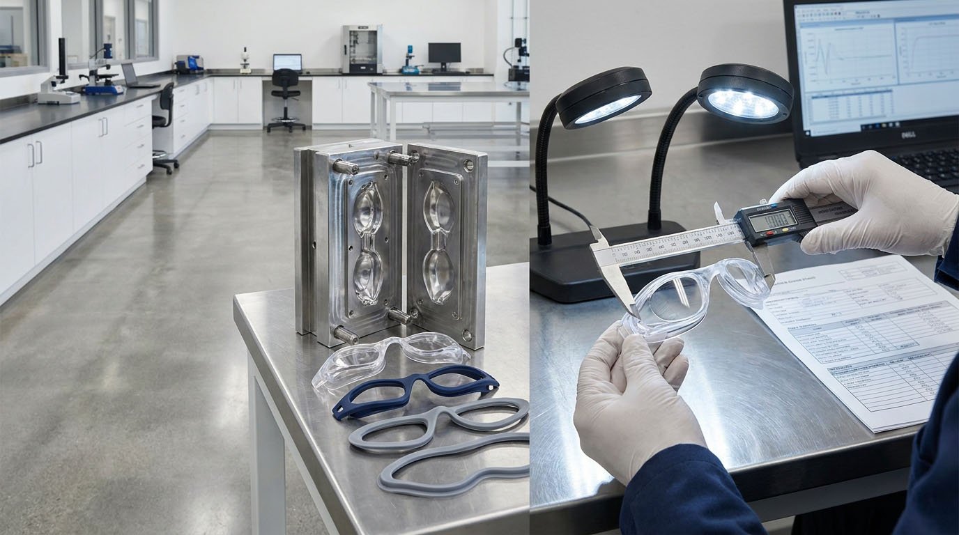
The first trial should examine dimensions, appearance, component interfaces, and molding defects against the approved engineering requirements.
Common findings include:
Flash: Excess material around mold parting lines can affect appearance, assembly, or surfaces that contact the swimmer.
Warpage: Uneven cooling or residual stress may affect lens shape, frame alignment, or component fit.
Short Fill: Incomplete cavity filling can leave features missing or structurally incomplete.
Sink Marks: Local depressions may appear where the molding geometry or processing conditions create uneven material contraction.
Dimensional Mismatch: A molded lens, frame, or gasket may not assemble as expected because its actual dimensions differ from the approved specification.
Optical components also require appropriate inspection for surface defects and visual distortion.
Separate Tooling Problems From Process Problems
A T1 defect does not automatically mean the mold needs to be rebuilt.
Engineers should first determine whether the problem originates from part geometry, material behavior, tooling condition, or process settings.
For example, warpage may involve cooling conditions, material selection, or wall-thickness distribution.
A dimension outside specification may require a tooling correction, but it may also need investigation of processing conditions and measurement methods.
Corrections should therefore follow root-cause analysis rather than trial-and-error adjustments.
How Are T1 Corrections Documented?
A useful trial report identifies the affected component, the measured problem, the approved requirement, the suspected cause, and the corrective action.
After changes are completed, the relevant features should be rechecked during a subsequent trial.
The purpose of T1, T2, or further trials is not to reach a predetermined number of revisions.
The goal is to demonstrate that the tooling can produce acceptable components consistently.
Step 6: Approve the Mold for Production
Mold approval is a formal engineering decision.
One visually acceptable sample is not enough if the tooling cannot repeatedly produce components that meet the agreed requirements.
Before release, the manufacturer should verify that the required corrections have been completed and the resulting components satisfy the project acceptance criteria.
What Should Be Included in Mold Approval?
A practical approval record connects each engineering milestone to its supporting evidence.
| Approval Gate | Required Evidence | Buyer Decision |
|---|---|---|
| CAD Release | Controlled drawings and approved materials | Approve the design |
| DFM Review | Documented engineering findings | Accept design changes |
| Pre-Tooling Validation | Prototype evaluation record | Authorize tooling |
| T1 / Follow-Up Trials | Inspection reports and correction records | Accept or request corrections |
| Final Tooling Review | Representative approved parts and required verification results | Authorize mold release |
Acceptance criteria should be established for each project rather than based only on general visual inspection.
Confirm Molded Components Against the Approved Design
Final verification may include dimensional inspection, component assembly, gasket alignment, lens condition, and other agreed functional checks.
Where performance depends on production-representative materials and processes, appropriate functional testing must also be completed before product release.
For example, a gasket’s actual sealing behavior must be evaluated using suitable finished components, not inferred solely from CAD dimensions.
Record the Final Approved Revision
The manufacturer should retain the approved CAD revision, applicable tooling records, trial results, corrective actions, and reference samples.
These records help prevent confusion when the mold is maintained, modified, or used for repeat production.
What Happens After Mold Approval?
The approved mold moves into production preparation.
Further activities may include process qualification, product testing, pilot production, and establishing inspection requirements.
Those activities belong to the broader manufacturing workflow rather than the CAD-to-mold engineering stage.
For the complete production handoff, see our Swimming Goggles OEM Process.
Common CAD-to-Mold Mistakes Brands Should Avoid
Many tooling delays originate from decisions made before the first mold trial.
Approving Appearance Without Engineering Review
A visually attractive CAD rendering does not demonstrate manufacturability.
Brands should request a DFM review before authorizing production tooling.
Changing Component Geometry After Tooling Begins
Even small changes to a lens edge, gasket interface, or strap attachment can affect the mold.
The potential consequences should be reviewed before approving a design revision.
Treating Prototype Fit as Final Molded Performance
Prototype materials may behave differently from molded production materials.
The final sealing and assembly performance must be verified with suitable molded samples.
Approving T1 Based Only on Appearance
A good-looking trial sample may still have dimensional or assembly problems.
Tooling approval should rely on agreed inspection and functional evidence.
Failing to Control CAD Revisions
If the brand and manufacturer use different drawing revisions, tooling corrections may solve the wrong problem.
Clear revision records are essential throughout the engineering process.
Frequently Asked Questions
Can a Swimming Goggle CAD Design Go Directly to Mold Making?
A finalized CAD design can move toward mold engineering after the required DFM and pre-tooling checks have been completed.
However, visual CAD approval alone should not replace these reviews.
What Is DFM in Swimming Goggle Manufacturing?
DFM stands for Design for Manufacturing. It evaluates whether a product can be manufactured with the intended materials, molding methods, dimensions, and assembly requirements.
It helps identify engineering risks before tooling fabrication.
Can a Swimming Goggle Mold Be Modified After T1?
Yes, many tooling issues can be corrected after an initial trial.
However, the feasibility and cost of modifications depend on mold construction, the affected feature, and the required geometry change.
Some corrections are straightforward; others may require major insert changes or new tooling.
How Many Mold Trials Are Needed?
There is no universal number.
Some tools meet their requirements after limited adjustment, while more complex designs may need additional trials.
The appropriate endpoint is meeting documented acceptance criteria, not completing a fixed number of trial rounds.
Does Mold Approval Mean the Goggles Are Ready for Mass Production?
Not necessarily.
Mold approval confirms that the tooling has met its defined acceptance requirements.
The finished product may still require assembly validation, functional testing, process qualification, and production-quality approval before commercial manufacturing begins.
Conclusion
Developing a new swimming goggle mold requires more than converting a CAD model into a steel cavity.
The process must address manufacturability, component interfaces, material behavior, physical validation, trial molding, and engineering approval.
A structured CAD-to-mold workflow helps brands identify design problems before investing further in tooling and production.
At Jerry, our in-house engineering, mold-making, injection molding, and silicone processing capabilities support custom swimming goggle development.
If your brand is preparing a proprietary goggle design, our OEM & ODM manufacturing team can help review your CAD files, evaluate tooling feasibility, and plan the next engineering steps before production begins.